LawnConnect
A simple Raspberry Pi powered lawn light controller
Never have dark outside lighting again!!!
LawnConnect automatically controls and monitors your lawn lights and lets you know when something is wrong
 Thanks HACKADAY for the BLOG Entry
Features:
- Automatically Turns on Lights at Sunset using 15Amp/250v Relay
- Turns off lights a random time 6-9 hours later
- A Web Interface for monitoring and manual turning on and off lights
- Detects when a Light has burnt out using MCP3008 10Bit 8 Channel ADC
- Sends text messages when a light is out.
- Accounts for daylight savings time
Latest Updates:
15 Oct 2016: The calibrate button on the web page is now functional.
Description:
Have you ever went outside and noticed one or maybe all your lawn lights were burnt out? This happened to me a little while ago. I went outside at night and noticed all 12 of my lawnscape lights were burnt out. Instead of being better at inspecting my yard at night, I decided there had to be a better way and a perfect project for the Raspberry Pi. This Raspberry Pi project is a simple solution that will ensure you have complete control of your lights, even when you aren't around. Try this simple but powerful internet of things project using the Raspberry pi.
The Rasberry pi will control all the turn on and off of lights and will continually monitor the system power to determine if a light is not working. On the event a light is not working or burnt out, a text message will be sent to the phone number of your choice telling you of the problem.
Through a simple web application, you can remotely monitor the status and control the turn on and off of the system. Otherwise, the Raspberry pi will turn on your lights exactly at sunset each night and will turn them off a random time between 6 and 9 hours later.
Web Application:
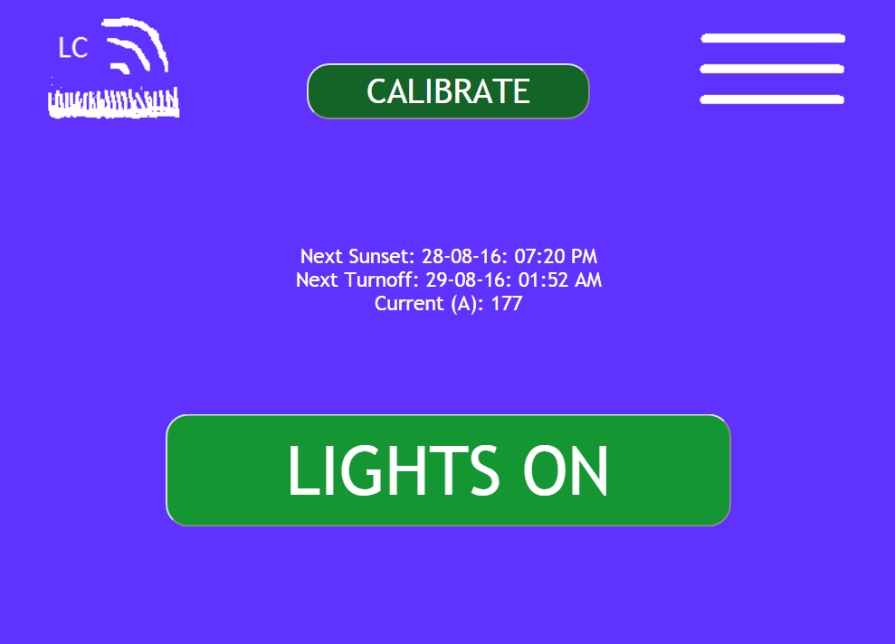
The web application, hosted by the Raspberry Pi, gives a status of the system. The Lights On button is used to turn on and off the lights. Text box messages tell when the lights will be turned on and off next. there is a current monitor that shows the current being used the lawn lights. A calibrate button will be used to calibrate the system at anytime. The sysetm will automatically calibrate when powered up for the first time. On this setup, it will detect if a 9Watt or larger Lawn Light has is burned out. Simple adjustments can be done to customize it to your system.
Block Diagram

Current Senor Board
The current sensor board will monitor the AC primary of the Lawn Light system. A current transformer monitors the signal and converts the signal into a low voltage AC wave that the MCP3008 10Bit ADC can read. The ADC reads the AC signal many times to find the peak value. This peak value represents the power in the system.
Relay Board
The HOT AC Wire of the Lawn Lights is controled by a 15A, 250v relay. the Raspberry Pi GPIO signals then connects to the relay board control inputs to control the individual relays. CAUTION. EXTREME CARE MUST BE TAKEN WORKING WITH PRIMARY AC SIGNALS. TOUCHING THESE LINES WITHOUT PROPER PRECAUTION CAN KILL. IF YOU HAVE ANY DOUBT, DON'T DO IT. ALWAYS CHECKOUT OPERATION OF THE RELAY FIRST WITHOUT AC POWER BEFORE TRYING FULL POWER.
RPi Power Supply
A 2 Amp power supply is recommended. This power supply is always on and provides power to the Rasberry Pi and all the other LawnConnect Control circuitry.
Raspberry Pi
A model B+ is used. This Raspberry Pi needs to be setup with Raspbian distribution and to auto connect to the wifi system.
Wiring Diagram:
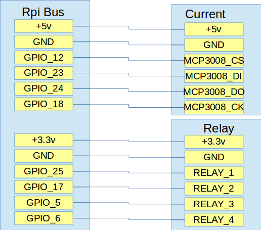
This is how the Raspberry Pi is connected to the sensor board schematic and the relay board
BOM:
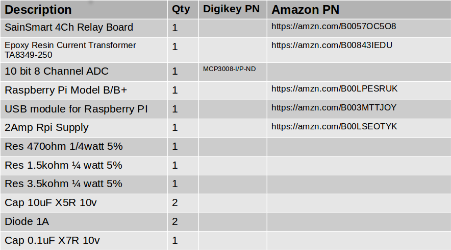
The major components for the project are listed below
Sensor Board Schematic
The current sensor board connects the secondary of the current transformer to an analog to digital converter (ADC). The ADC converts the current into a digital signal that can be sampled by the Raspberry Pi
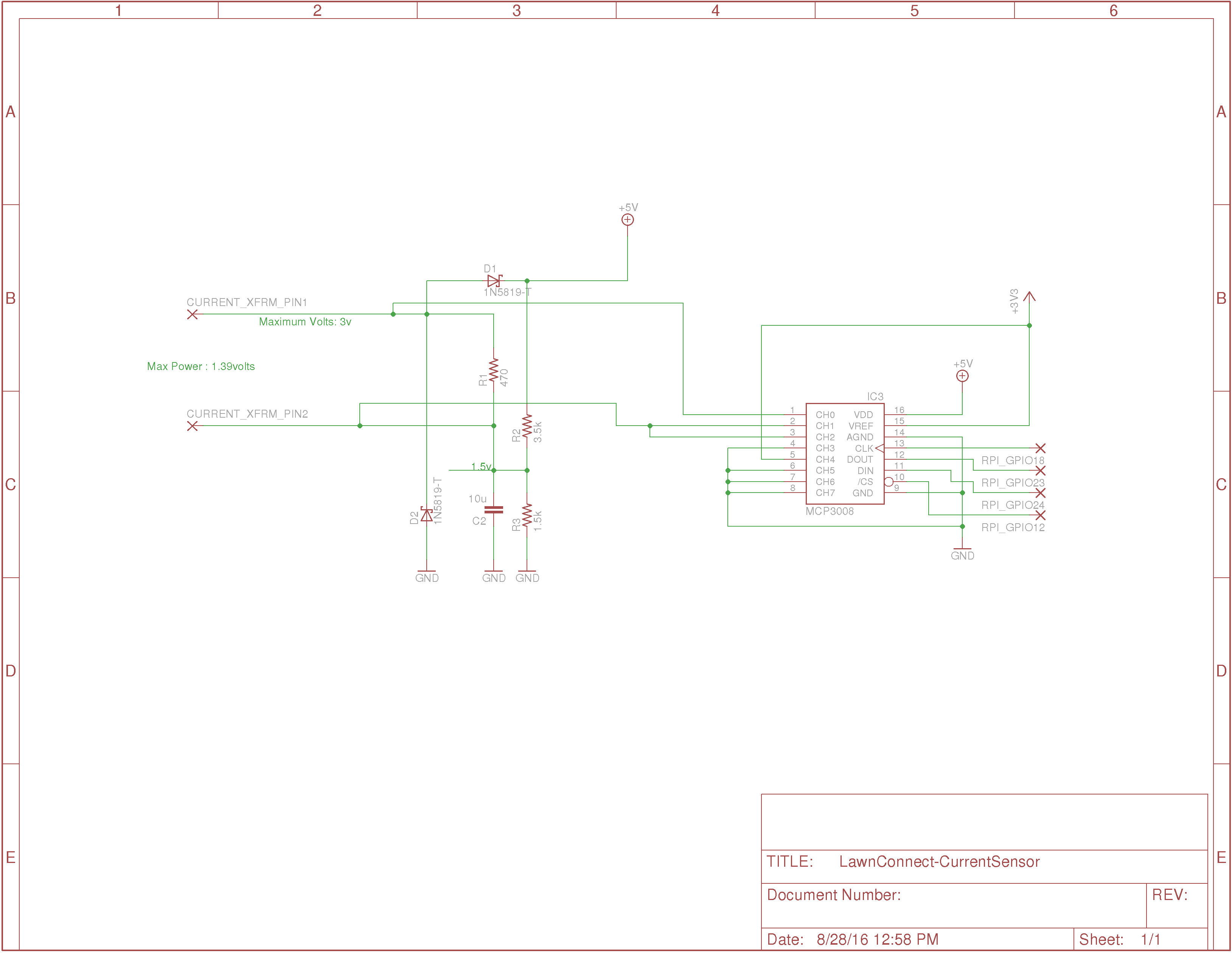
This simple schematic accurately reads the current of the lawn lights, protects against extreme conditions, and uses the signal processing capability of the raspberry pi to minimize components. The heart of the circuit is the 2500 to 1 turns ratio current transformer that samples the primary current with a secondary current that is 1/2500th the primary current value. The secondary current is converted into a voltage by the 470 ohm resistor (R1). Different values of R1 will provide different system gains in reading the primary current. Smaller values will provide less voltage. Resistors over 470ohm are not recommended as they may degrade the 1% current transforer accuracy rating. R1 was chosen in this case to accurately read currents up to 5amps RMS (approximately 600Watts of power from 120VAC outlet). The two diodes, D1 and D2, will protect the ADC from extreme current surges. They clamp the current to the 3.3v power supply or to the circuit ground and ensure the MCP3008 inputs don't get over their absolute maximum values. Channel 0 and Channel 1 of the MCP3008 ADC, connected to each end of R1, are used to convert the voltage into a digital signal and transmit it to the Raspberry pi via an SPI interface. The R1 voltage read by the ADC is a sinusoidal voltage. It could have been converted into a rectified signal before being read, but this would take additional parts and reduce accuracy. So instead, the Raspberry Pi is used to obtain the RMS current from this sinusoidal signal. The Raspberry pi simply takes 100 consequtive readings to find the peak of the AC signal. We adjusted the number of reading to ensure we were sampling the complete 60Hz sinusoidal signal. The 10 bit ADC peak to peak sinusoidal readings are equally spaced across 3.3v, so the volts/bit = ADC READING times (3.3v/1024). Since this is the voltage being read across the 470 ohm resistor, the current reading is obtained by dividing by this resistance (470ohms). This represents the peak current on the secondary. You have to multiply this by the current transformer turns ratio (2500:1) to obtain the current on the primary. Multiply this by 0.707 to obtain RMS current. The result is RMS CURRENT = ADC_READING times (3.3v/1024/470(2500)(.707)). Using the power of the Raspberry pi, this schematic monitors the peak and RMS currents of the lawn lights without a lot of addition components.
For outside low voltage halogen lighting, where the reactance of the system is minimal, this RMS current can be multiplied by AC voltage (i.e. 120volts) to obtan the power being consumed.
Software
The software uses a python program to monitor the current through a SPI interface and the relays through simple GPIO pins. The simple python web server, (i.e. python -m CGIHTTPServer 8010) is used to service web requests. The client webpage uses javascript to monitor user inputs and output data from the monitor program. Communication between the web server and the main program is performed by datafiles.
The setup is straighforward. You need to setup the Rasbperry Pi to automatically connect to your wifi system. Then you also need to be able to access the Raspberry pi as a headless system. There are plenty of guides available on the internet. The key is that you can log into the system via ssh pi@xxx.xxx.1.xxx where xxx.xxx.1.xxx is the IP address of your Raspberry Pi.
Download the github software into the /home/pi directory.
git clone https://github.com/drkmsmithjr/LConnect.git
Edit and setup the crontab to automatically start the boot.sh script.
crontab -e
edit this file with the following command
@reboot /home/pi/LConnect/boot.sh
Reboot the system to get things started.
sudo reboot
Open a browser and find the IP address of the Raspberry Pi to access the webpage. You need the :8010 port extension to access the browser
RPIADDRESS:8010/LawnConnectIndex.html
Setting up the Correct GPS Location
You will need to put your Longitude and Latitude into the LawnConnect.py code by setting the o.lat and o.long parameters
    o.lat = '33.4672'
    o.long = '-117.6981'
Twillo Account Setup
The LawnConnect will sent an SMS message to your cell phone using Twillo Account. You will need to get a Free Twillo Account at https://www.twilio.com. After getting an account, get the twillo Phone Number, Account Number, and Token and place them into the twilloaccount.py file. this file is not in the Git download but can easily be generated as follows:
#!/usr/bin/python
# where to put the twillo account information
Taccount= 'twillo_account'
Ttoken ='twillo_token'
Tnumber = 'twillo number'
To_number = 'Number to Call'
save this twilloaccount.py file into the /home/pi/LConnect directory
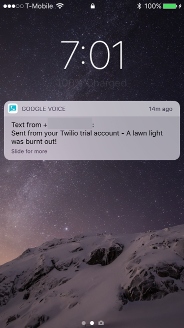
When the LawnConnect detects when one or more lights are out, a text will be sent to the number you choose. It will repeat this text each night until you replace the light or a new calibration is performed either by pressing the calibration button on the webpage or by restarting the software. Here is an example text to an iphone:
Web Software
Calibrate Button
The Calibrate button, when pushed, will set the reading of the light current and store this value for comparison. A future reading below this baseline value will indicate that a light has burnt out and will send a text message indicating the event.
You are all set. Good Luck and let me know if you have any questions.
The webpage for the project is located at https://drkmsmithjr.github.io/LConnect